You know the setup. You flip the switch by the door, the light turns on. You walk into the room and flip the switch on the other wall, the light turns off. Two switches. One light. It feels like magic until you realize it’s just physics and a specific type of wiring.
Most people think a switch is just a simple on-off gate. That’s true for standard switches. But for this kind of control, you need something different. You need a three-way switch. And you need the right wire to make them talk to each other.
The Hardware You Need
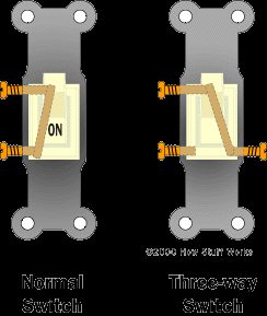
To get two switches talking to one light, you can’t just grab any switch from the rack. You need three-way switches. They look similar to standard switches, but the terminals are different.
A normal switch has two terminals. Flip it, and you connect or disconnect the circuit. Simple. A three-way switch has three terminals. It acts like a selector. It connects the common terminal to one of the two traveler terminals. Flip the switch, and it jumps to the other traveler. That’s the core mechanism.
You also need special wire. Not just any Romex. You need a cable that has four conductors: black, white, red, and the bare ground. The red wire is the key. It’s an extra insulated wire inside the sheath. Without it, you can’t send the signal between the two switches.
How the Circuit Actually Works
Let’s break down the path the electricity takes.
- Power Entry: The circuit starts at your fuse panel or breaker box. A standard two-wire cable (black and white) runs to the first three-way switch. The black wire is the “hot” line. It brings the power in.
- The First Switch: The hot wire connects to the common terminal on the left switch. The red and black wires in the three-way cable leave this switch and head toward the second switch. These are called “traveler” wires. They carry the signal back and forth.
- The Second Switch: The traveler wires plug into the two traveler terminals on the right switch. The common terminal on this switch then sends power out to the light fixture.
- The Light: A standard cable runs from the second switch to the light. The white wire is the neutral. The black wire is the hot wire that actually powers the bulb.
The white wire in the three-way cable usually acts as a ground return or a neutral for the switch itself, depending on the exact configuration. But the red and black wires are the busybodies. They carry the output from the terminals in the left switch to the right switch.
Why This Matters for DIY
If you’re planning to install this yourself, don’t skip the safety step. Turn off the breaker. Always. Test the wires with a non-contact tester before you touch anything.
You might wonder why you can’t just use two standard switches. You can’t. Standard switches don’t have the extra terminal to handle the traveler wires. Without the red wire in the cable, you can’t complete the loop between the two locations.
The system relies on the three-way switches to toggle the circuit path. One switch sends power through the black traveler. The other sends it through the red. Depending
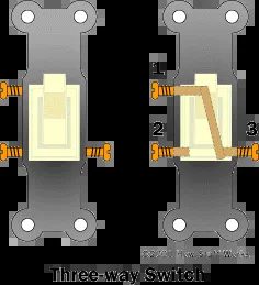
When the toggle is flipped up, terminals one and three connect. Flip it down, and the circuit shifts to link terminals two and three. Trace the wires in the previous diagram and you will see the light stays dark. Flip either switch, and the bulb glows. Flip it again, and it dies. The mechanism is surprisingly straightforward once you strip away the wall and see the metal contacts working.
Power does not always start at the switch. You might find the feed coming from the fuse box directly into the light fixture. In that case, the two switches sit in series, one after the other. Sometimes the power hits the fixture first, then splits into a parallel arrangement of switches. The logic holds up regardless of the path the electricity takes.
If you are staring at a wall box trying to figure out what a previous electrician installed, guessing won’t work. You need a continuity detector or an ohmmeter to read the hidden connections. This is the only reliable way to reverse-engineer the setup.
Warning: Turn the power off at the fuse panel before touching any wires. Even a low-voltage test requires a de-energized circuit to avoid shock or blowing a fuse.
Once the power is cut, the tester reveals the truth. If you grasp the basic logic of how three-way switches toggle between terminals, identifying the specific wiring becomes a simple exercise. You can trace the travelers and common connections with confidence.
Curiosity satisfied? Maybe. But if you want to dig deeper into the hardware behind the wall, there is plenty to explore.
Related HowStuffWorks Articles
- How Light Bulbs Work
- How Fluorescent Lamps Work
- How Power Distribution Grids Work
- How Light Works
- How does a three-way light bulb work?
- How do touch-sensitive lamps work?
More Great Links
- HandymanWire: Wiring a 3-Way or 4-Way Switch
- The Magic of a “Three Way” Switch
- Three-Way Switch Circuits
- The Three-Way Switch How-To